 简体中文
简体中文 English
 русский
 Español
Fubang is a professional manufacturer specializing in the design, production and sales of stainless steel chains.
Our A series short pitch precision roller chains comply with various international standards and are...
See DetailsContent
A drive chain, also called a driving chain, is a mechanical power transmission device that transfers rotational force from one component to another through a series of interconnected links. These chains are essential in motorcycles, bicycles, industrial machinery, and conveyor systems, where they deliver efficiency rates of 95-98% under optimal conditions. While the terms "drive chain" and "driving chain" are often used interchangeably, they both refer to the same fundamental component—a roller chain designed to transmit mechanical power reliably and efficiently.
The primary function of these chains is to connect a driving sprocket (powered by a motor or engine) to a driven sprocket, converting rotational energy into mechanical motion. Unlike belt drives, chains maintain constant speed ratios without slippage, making them ideal for applications requiring precise power transmission. Common examples include motorcycle rear-wheel drives, bicycle drivetrains, and industrial conveyor systems where consistent performance is critical.
Different applications require specific chain designs optimized for load capacity, speed, and environmental conditions. Understanding these variations helps in selecting the appropriate chain for your needs.
Roller chains are the most common type, featuring cylindrical rollers between link plates that reduce friction with sprocket teeth. The ANSI #40 and #50 chains are industry standards for motorcycles and light industrial equipment, with pitch measurements of 1/2 inch and 5/8 inch respectively. These chains can handle loads ranging from 2,000 to 18,000 pounds depending on size and construction.
Silent chains, also known as inverted-tooth chains, use specially shaped teeth that mesh smoothly with sprockets, producing minimal noise. They're commonly found in automotive timing systems and high-speed industrial applications where noise reduction is critical, operating effectively at speeds up to 10,000 feet per minute.
These sealed chains incorporate rubber rings between link plates to retain lubrication and exclude contaminants. O-ring chains can last 3-4 times longer than standard chains in motorcycle applications, while X-ring designs offer even better performance with reduced friction and extended service life of up to 20,000 miles on motorcycles.
| Chain Type | Primary Use | Typical Lifespan | Maintenance Level |
|---|---|---|---|
| Standard Roller | General industrial, bicycles | 5,000-8,000 miles | High |
| O-Ring | Motorcycles, heavy-duty | 15,000-18,000 miles | Medium |
| X-Ring | High-performance motorcycles | 18,000-20,000+ miles | Low |
| Silent Chain | Automotive timing, precision drives | 100,000+ miles | Very Low |
Selecting the appropriate driving chain requires careful consideration of several technical factors that directly impact performance and longevity.
Calculate the working load by considering both static weight and dynamic forces. For motorcycles, multiply engine horsepower by 5,000 and divide by chain speed in feet per minute to determine minimum tensile strength. Industrial applications typically require a safety factor of 7:1 to 10:1 between rated breaking strength and working load.
Standard roller chains perform well up to 1,000 feet per minute, while specialized designs handle speeds exceeding 3,000 feet per minute. For outdoor or harsh environments, corrosion-resistant chains made from stainless steel or nickel-plated materials prevent premature failure. Marine applications benefit from chains with 316-grade stainless steel that resists saltwater corrosion.
Chain pitch must match sprocket tooth spacing exactly. Common motorcycle pitches include 428 (1/2 inch), 520 (5/8 inch), and 530 (5/8 inch with larger rollers). Mismatched components cause accelerated wear and potential failure. Always verify that chain width corresponds to sprocket groove dimensions, with typical tolerances of ±0.005 inches.
Proper maintenance extends chain life significantly and prevents costly breakdowns. A well-maintained chain can outlast a neglected chain by 200-300%.
Motorcycle chains require lubrication every 400-600 miles or after wet riding conditions. Apply lubricant to the inside of the chain while rotating the wheel slowly, allowing the product to penetrate between rollers and pins. For industrial chains, establish lubrication intervals based on operating hours, typically every 8-40 hours depending on speed and load. Use lubricants specifically formulated for chain drives, as general-purpose oils lack the necessary tackiness and extreme-pressure additives.
Chains stretch during use and require periodic adjustment. Motorcycle chains typically need 20-30mm of vertical play at the midpoint between sprockets. Too tight causes bearing wear and power loss, while excessive slack leads to sprocket tooth damage and potential derailment. Check tension every 500-1,000 miles and adjust according to manufacturer specifications.
Regular inspections identify wear before failure occurs. Key warning signs include:
Replace chains showing any of these symptoms immediately to prevent damage to other drivetrain components.
Understanding typical chain failures helps prevent downtime and maintains system efficiency.
Chains wearing faster than expected usually indicate inadequate lubrication, misalignment, or overloading. Misalignment as small as 0.5 degrees between sprockets can reduce chain life by 50%. Use a straightedge or laser alignment tool to ensure sprockets are parallel within manufacturer tolerances, typically 1/16 inch per foot of center distance.
Unusual sounds often stem from improper tension, worn sprockets, or contamination. A properly tensioned chain runs quietly at all speeds. If noise persists after adjustment, inspect sprocket teeth for wear patterns. Industrial chains operating in dusty environments benefit from enclosed guards and automated lubrication systems that maintain cleanliness and consistent lubrication.
Catastrophic failure results from exceeding load limits, shock loading, or fatigue from cyclic stress. Always replace chains and sprockets as matched sets, as worn sprockets accelerate new chain wear by up to 400%. For critical applications, implement predictive maintenance programs that monitor chain elongation and establish replacement schedules based on actual wear rates rather than time alone.
Maximizing drive chain efficiency requires attention to design parameters and operational practices that minimize energy losses.
The number of teeth on driving and driven sprockets determines speed ratio and affects chain life. Minimum recommended sprocket size is 17 teeth to reduce polygon effect and wear. Smaller sprockets increase chain articulation frequency, accelerating fatigue. For motorcycle applications, changing rear sprocket size by one tooth alters final drive ratio by approximately 3-6%, affecting both acceleration and top speed.
Ideal center distance between sprockets equals 30-50 times the chain pitch. This range balances tension adjustment capability with efficient power transmission. Shorter distances limit adjustment range, while excessive distances increase weight and cost. Calculate exact chain length in pitches using the formula: L = 2C/P + (N+n)/2 + (N-n)²/(4π²C/P), where C is center distance, P is pitch, N is large sprocket teeth, and n is small sprocket teeth.
Operating temperature affects lubrication effectiveness and material properties. Standard chains function optimally between -20°F and 180°F. High-temperature applications require special lubricants and heat-treated components. Conversely, cold environments demand low-viscosity lubricants that maintain fluidity. Monitor operating temperature with infrared thermometers and adjust lubrication intervals accordingly—higher temperatures accelerate lubricant breakdown.
Correct installation establishes the foundation for reliable chain operation and longevity.
Use dedicated chain breaking tools rather than improvised methods that damage link plates. When installing master links or connecting links, ensure clip openings face opposite the direction of rotation to prevent disengagement. Press-fit connecting links require specialized tools that apply uniform force across both pins simultaneously. Never reuse connecting links—always install new components during chain replacement.
New chains experience initial seating where components conform to each other. During the first 100-200 miles of motorcycle operation or 20 hours of industrial use, chains stretch more rapidly than during normal service. Check and adjust tension after this break-in period, then establish regular maintenance intervals. Some high-performance chains benefit from gradual load application during initial operation to allow proper seating without excessive stress.
After installation, verify alignment using the string method or laser tools. Place a straightedge against the drive sprocket face and extend it to the driven sprocket. Both sprockets should contact the straightedge equally across their width. Misalignment causes uneven wear and reduces efficiency by 5-15%. Adjust shaft positions or use shims to achieve proper alignment within 1mm over the entire center distance.
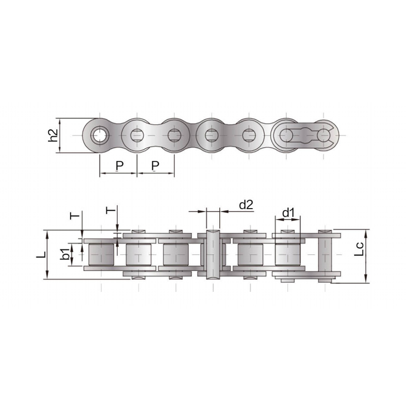
Our A series short pitch precision roller chains comply with various international standards and are...
See Details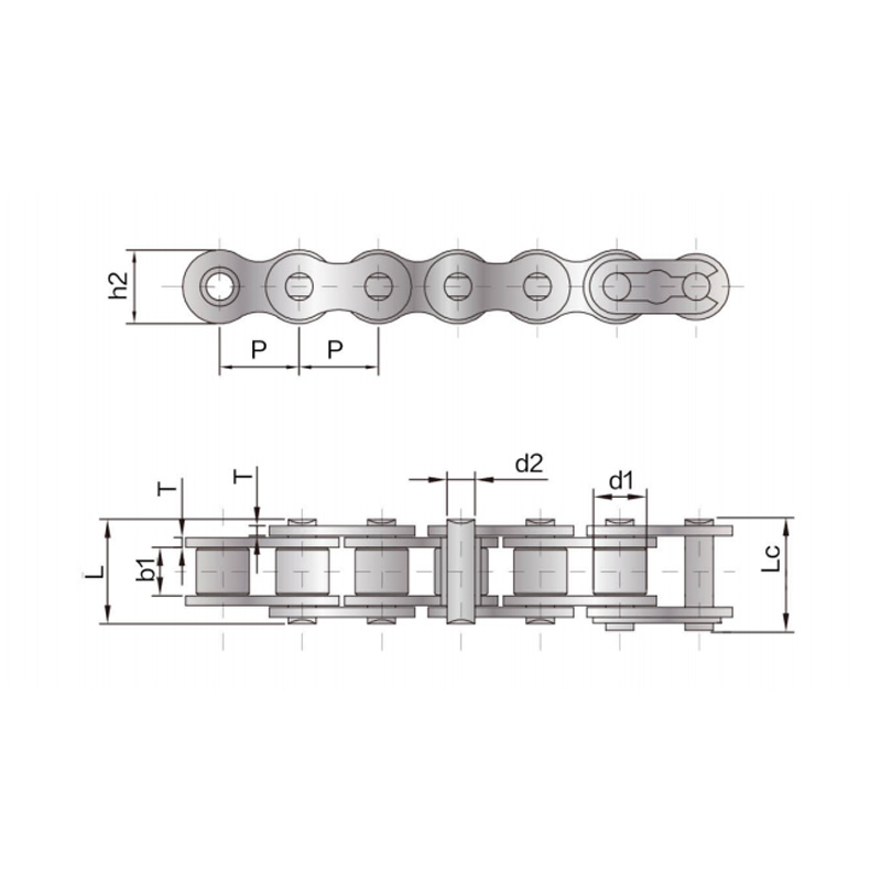
The tensile strength and fatigue strength of the B series short pitch precision roller chain reach 1...
See Details
The Heavy-duty precision roller chain adopts a thickened chain plate design based on the short-pitch...
See Details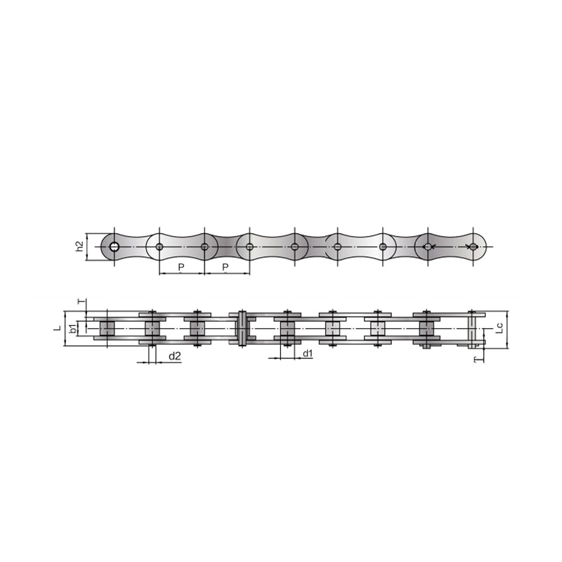
The double pitch driving chain complies with various international standards. The pitch of the doubl...
See Details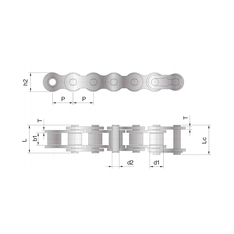
We also produce single row roller drive chains in more sizes and varieties. Customised products, sui...
See Details
Side bow chain refers to changing the size of parts in the design of short-pitch precision roller ch...
See Details
The Anti-Sidebow chain for pushing window is a functional product with specially designed parts and ...
See Details
The A series short-pitch straight plate precision roller chain has a smaller pitch, a relatively lar...
See Details© Suzhou Fubang Machinery Chain Transmission Manufacturing Co., Ltd. Stainless Steel Roller Chains Manufacturers Conveyor Chains Suppliers
