 简体中文
 English
 русский
 Español

Fubang is a professional manufacturer specializing in the design, production and sales of stainless steel chains.
Our A series short pitch precision roller chains comply with various international standards and are...
See Details
Content
A caliper across two pin centres reads 12.70 mm, the side plate is stamped 40, and the OEM parts list says 08B. All three describe a half inch pitch chain, and only one of them will seat properly on the sprocket in front of you.
ANSI chain sizes are the easiest sizing system in power transmission to read, and the easiest to get half right. The number on the plate encodes pitch, but pitch alone tells you very little about whether a replacement will run: roller diameter, inner width and plate thickness decide whether the chain sits down in the tooth seat, carries the load and clears the guide rails. What follows is how the numbering actually works, where it stops being reliable, and what to put on a purchase enquiry so the wrong box never arrives.
Divide the ANSI number by 8 and you have the pitch in inches; multiply by 25.4 to get millimetres. Chain #40 is 4/8 in, or 12.70 mm. Chain #80 is 8/8 in, or 25.40 mm. Chain #160 is 16/8 in, or 50.80 mm. This single rule covers the whole A series from #25 upward and is the fastest way to sanity check a parts list.
Pitch in millimetres equals the chain number divided by 8, then multiplied by 25.4. The rule gives you the pitch. It does not give you the roller.
| ANSI number | Pitch (in) | Pitch (mm) | Roller diameter (mm) | Inner width (mm) |
|---|---|---|---|---|
| 25 | 1/4 | 6.35 | 3.30 | 3.18 |
| 35 | 3/8 | 9.525 | 5.08 | 4.78 |
| 40 | 1/2 | 12.70 | 7.92 | 7.85 |
| 41 | 1/2 | 12.70 | 7.77 | 6.35 |
| 50 | 5/8 | 15.875 | 10.16 | 9.40 |
| 60 | 3/4 | 19.05 | 11.91 | 12.57 |
| 80 | 1 | 25.40 | 15.88 | 15.75 |
| 100 | 1 1/4 | 31.75 | 19.05 | 18.90 |
| 120 | 1 1/2 | 38.10 | 22.23 | 25.22 |
Pitch progression, #25 to #120
#41 is the trap. It shares the 1/2 in pitch of #40, so a length cut for one will hang on the other, but its roller is 7.77 mm instead of 7.92 mm and its inner width is 6.35 mm instead of 7.85 mm. Run it on a #40 sprocket and the load lands on a narrow band of the tooth flank, wearing both parts faster than either would wear alone. #25, the smallest common size, is a bushed chain in the ANSI definition, and its 3.18 mm inner width leaves very little room for misalignment; the detailed #25 chain specification covers where that size genuinely belongs.
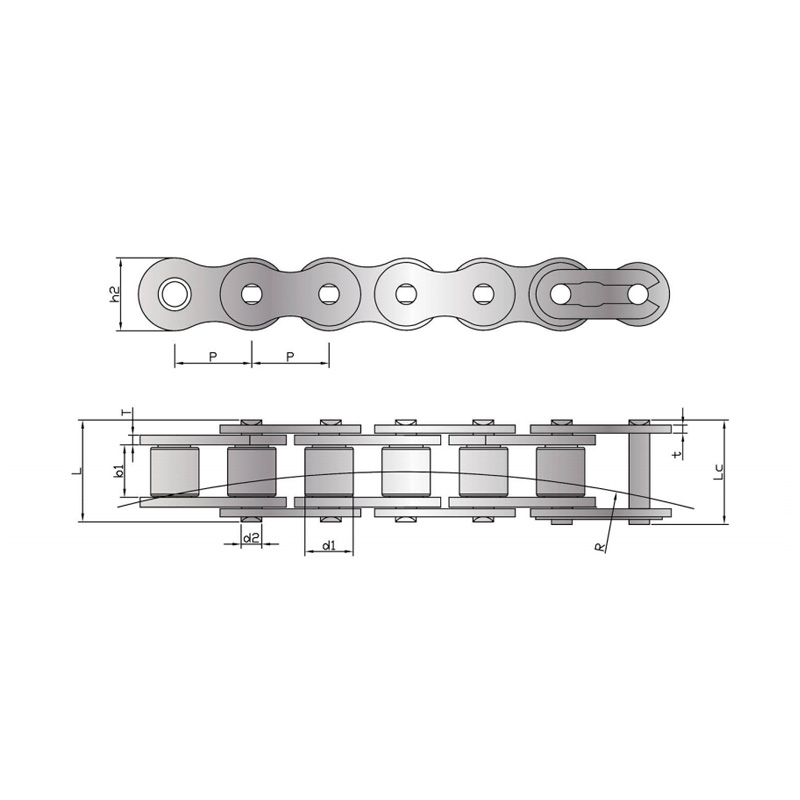 A-Series Short-Pitch Precision Roller ChainA-series precision roller chain for driving applications; verify roller diameter and inner width as well as pitch when matching existing sprockets.View Product →
The A series (ANSI) and the B series (BS and DIN) use the same inch based pitch steps, but the roller dimensions differ, so a #40 and an 08B will hang on the same shaft and run badly on the same sprocket. Pitch gets you in the door; the roller decides whether the chain sits in the tooth seat.
ANSI #40
BS 08B
The gap widens at small sizes. #35 uses a 5.08 mm roller, while 06B at the identical 9.525 mm pitch uses 6.35 mm, a 25 percent difference in the one feature that transfers load into the tooth. Sprockets are cut to the roller, not to the pitch, so a B series chain on an A series sprocket rides high on the tips and wears quickly. Where a plant mixes imported and domestic machinery, log the standard as well as the number against every chain on the line.
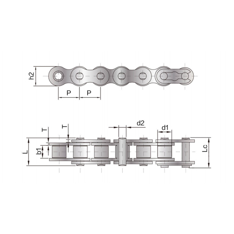 B-Series Short-Pitch Precision Roller ChainB-series single-row driving chain for mechanical engineering; confirm roller diameter and standard, since B-series sprockets differ from A-series despite similar pitch.View Product →
Measure across ten pitches, divide by ten to get the pitch, then confirm the roller diameter: pitch narrows the chain to a family, and the roller pins it to one number.
Clean a straight run. Grease and kinked links distort a caliper reading, so wipe down eight to twelve links on a flat surface first.
Count spaces, not pins. Ten pitches means eleven pin centres. Counting pins instead of spaces is the most common source of a wrong pitch figure.
Measure pin centre to pin centre across the whole span with a caliper, or with a steel rule against a straight edge on longer chains.
Divide by the number of pitches. A span of 127.3 mm over ten pitches gives 12.73 mm, within 0.03 mm of the 12.70 mm nominal for the #40 family.
Measure the roller diameter across the outside of two adjacent rollers. A reading near 7.9 mm confirms #40; a reading near 7.8 mm points to #41.
Check the inner width between the inner plates. Width separates chains that share a pitch and a roller but differ in load capacity.
Pitch grows as pins and bushings wear, so the same measurement doubles as a wear check. Drive chains are usually retired at around 1 percent elongation, and conveyor chains in clean service can run to roughly 1.5 percent, but a chain past its limit has already reshaped the sprocket to match its stretched pitch.
A sprocket is defined by pitch and roller diameter together, so a sprocket that accepts one 12.70 mm chain will not necessarily accept another. Tooth count then sets the ratio, and flank wear decides how long the new chain lasts.
 Customizable Chain Sprockets for Mechanical TransmissionSprockets in flat, single-sided hub, double-sided hub and assembly types, with customization for chemical, textile, food-processing, instrumentation and petroleum applications.View Product →
Send the chain number with its standard, the measured pitch and roller diameter, the strand count, the length in pitches and the material grade. A number on its own leaves too much to assumption, especially where the same number exists in stainless and carbon steel with very different load ratings.
If the stamping is gone and the measurement sits between two sizes, send the span, the roller diameter and a photo of the sprocket to our engineering team and we will match it against the standard before anything is cut.
No. Both share a 12.70 mm pitch, but #40 uses a 7.92 mm roller and a 7.85 mm inner width, while 08B uses an 8.51 mm roller and a 7.75 mm inner width. The chain will physically hang on the other sprocket, but the roller will not seat correctly in the tooth.
Divide the number by 8 to get the pitch in inches and multiply by 25.4. #50 is 5/8 in or 15.875 mm, #60 is 3/4 in or 19.05 mm, and #100 is 1 1/4 in or 31.75 mm.
Only if the sprocket and the load allow it. #41 shares the 1/2 in pitch but has thinner plates, a 7.77 mm roller and a 6.35 mm inner width, which means lower tensile strength and a narrower bearing surface on the tooth.
The suffix gives the strand count. 40-1 is simplex, 40-2 is duplex and 40-3 is triplex. Pitch and roller diameter stay the same, so the sprocket must be cut for the matching strand count.
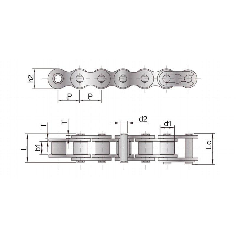
Our A series short pitch precision roller chains comply with various international standards and are...
See Details
The tensile strength and fatigue strength of the B series short pitch precision roller chain reach 1...
See Details
The Heavy-duty precision roller chain adopts a thickened chain plate design based on the short-pitch...
See Details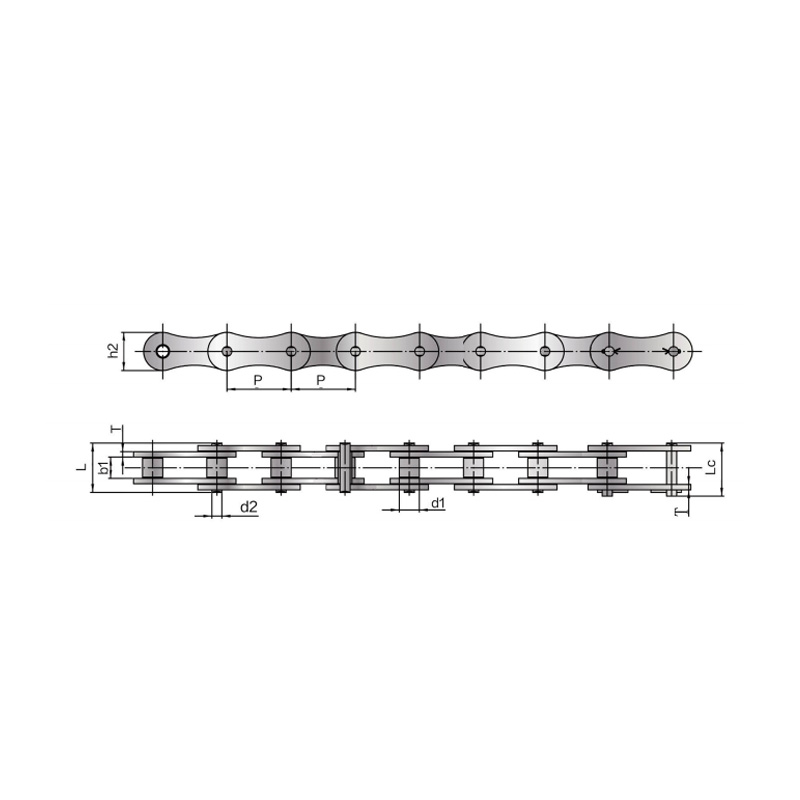
The double pitch driving chain complies with various international standards. The pitch of the doubl...
See Details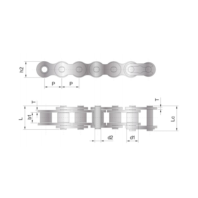
We also produce single row roller drive chains in more sizes and varieties. Customised products, sui...
See Details
Side bow chain refers to changing the size of parts in the design of short-pitch precision roller ch...
See Details
The Anti-Sidebow chain for pushing window is a functional product with specially designed parts and ...
See Details
The A series short-pitch straight plate precision roller chain has a smaller pitch, a relatively lar...
See Details© Suzhou Fubang Machinery Chain Transmission Manufacturing Co., Ltd. Stainless Steel Roller Chains Manufacturers Conveyor Chains Suppliers
